Boolean Logic
Logic Gates
Logic Gate Symbols
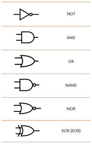
The shapes used in logic gates correlate with their names. A small circle means NOT and can be seen in gates with the letter N in them including the NOT gate itself. A curved line is used for gates with an X which stands for exclusive in their name.
The diagram below shows all gates except the XNOR gate.

Logic Gate Functions
All logic gates take 2 inputs and produce 1 output except for a NOT gate which only takes 1 input. Each wire connected to a logic gate carries a binary value of 0 (false) or 1 (true).
NOT
A single input is inverted.
| A | X |
|---|---|
| 0 | 1 |
| 1 | 0 |
AND
Both inputs must be 1 to output 1.
| A | B | X |
|---|---|---|
| 0 | 0 | 0 |
| 1 | 0 | 0 |
| 0 | 1 | 0 |
| 1 | 1 | 1 |
OR
At least a single input must be 1 to output 1.
| A | B | X |
|---|---|---|
| 0 | 0 | 0 |
| 1 | 0 | 1 |
| 0 | 1 | 1 |
| 1 | 1 | 1 |
XOR
Both inputs must be different to output 1.
| A | B | X |
|---|---|---|
| 0 | 0 | 0 |
| 1 | 0 | 1 |
| 0 | 1 | 1 |
| 1 | 1 | 0 |
NAND
At least a single input must be 0 to output 1.
| A | B | X |
|---|---|---|
| 0 | 0 | 1 |
| 1 | 0 | 1 |
| 0 | 1 | 1 |
| 1 | 1 | 0 |
NOR
Both inputs must be 0 to output 1.
| A | B | X |
|---|---|---|
| 0 | 0 | 1 |
| 1 | 0 | 0 |
| 0 | 1 | 0 |
| 1 | 1 | 0 |
XNOR
Both inputs must be the same to output 1.
| A | B | X |
|---|---|---|
| 0 | 0 | 1 |
| 1 | 0 | 0 |
| 0 | 1 | 0 |
| 1 | 1 | 1 |
Logic Circuit
A logic circuit is a system of logic gates connected to each other. Logic circuits often have 3 or more inputs and 1 output in IGCSE. Logic circuits must be drawn by using the correct symbol for each logic gate. There are some things to keep in mind while drawing thse diagrams.
- Logic expressions should not be simplified to make it easier to draw the logic circuit
- Some inputs may be used multiple times
- A dot must be placed at the intersection of 2 wires if they are connected to each other
- A curve may be used at the intersection of 2 wires to indicate that a wire is simply overlapping and not joining another wire
Truth Table
A truth table is used to show all the possible outputs of a logic gate or circuit for every possible input. In IGCSE, truth tables usually only involve 3 inputs (8 possible outputs). Converting a logic circuit into a logic expression may make it easier to complete truth tables.
Logic Expression
A logic expression is similar to a boolean expression in pseudocode. The logic gates are treated as operators and parentheses are used to group these operations. Operations inside the innermost parentheses must be calculated first just like order of operations in mathematics.
There are some strategies when it comes to converting circuits into expressions.
- The gate closest to the ouput is the last operation (outermost parantheses)
- It is easier to work backwards from the output towards the inputs